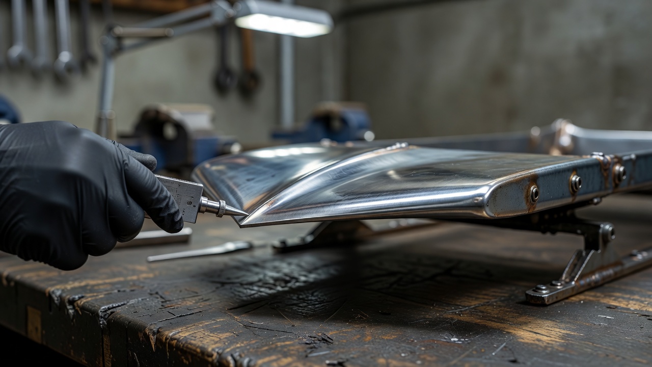
Start with the permitted design space
Before discussing runner preparation, identify the competition class, applicable rules and equipment inspection process. The International Bobsleigh & Skeleton Federation maintains the governing international bobsleigh documents. Requirements can change between editions, so a remembered dimension or workshop convention is not a sufficient design authority. Record the edition, clause and component identification against each compliance check. Consult the relevant officials when an interpretation affects eligibility.
Published requirements: IBSF downloads and international rules. This article deliberately does not reproduce a dimensional limit without its edition and context.
Separate three records. The requirement states what is permitted. The inspection procedure explains how conformity is assessed. The engineering hypothesis explains why a permitted variation might affect behaviour. Mixing these records encourages a common error: assuming that a plausible mechanism is either approved or beneficial before either point has been demonstrated.
Describe geometry before surface finish
A runner needs a coordinate system. Identify the longitudinal direction, transverse section, mounting references and the portion being evaluated. Profile, local form and assembled alignment describe different properties. A single radius value cannot express every departure from the intended shape, and a measurement taken at one station cannot establish consistency along the complete working length.
Use suitable metrology for the feature being inspected. A coordinate measurement system can support form assessment, while a surface instrument addresses a different scale of texture. Establish clean, stable supports and avoid clamping forces that distort the part. Repeat the setup to learn whether the fixture, rather than the runner, dominates the apparent difference. ISO 1101 provides geometrical tolerancing language; the ISO 21920 series addresses profile surface texture specification.
Method references: ISO 1101 and ISO 21920. Neither standard predicts ice friction.
A surface number needs its measurement settings
Surface roughness is not an intrinsic single-number verdict. The reported parameter depends on filtering, evaluation length, measurement direction and instrument response. Two readings bearing the same unit may not be comparable if these settings differ. Record the settings, trace direction and location so that a later inspection can reproduce the operation rather than merely repeat the instrument display.
Ice contact also involves an evolving environment. Temperature, local pressure, sliding speed and the condition of the ice can change the interface. A lower measured roughness therefore does not, by itself, justify a lower-resistance claim. Avoid treating a simplified friction model as a universal description of a loaded bobsleigh runner throughout a run.
Inspect the assembled load path
A runner belongs to an assembly containing supports, joints and a flexible structure. Establish how the sled is supported during inspection and how representative loads are introduced. Check whether the chosen fixture constrains a motion that would exist in service. Where appropriate, measure unloaded and loaded states separately, rather than subtracting one from the other without recording the setup.
Fastener condition, seating and mounting repeatability deserve the same attention as the runner surface. A small assembly change can alter alignment and invalidate a comparison attributed to finishing. Give every runner an identifier and maintain a history of assembly, inspection and permitted maintenance. A photograph helps locate an observation, but it is not a substitute for a measurement record with units and uncertainty.
Compare without inventing certainty
Begin with a baseline and a question narrow enough to test. For example, ask whether a documented preparation process produces a repeatable surface state before asking whether it changes sled behaviour. Use repeat measurements, a consistent cleaning protocol and controlled handling. Keep temperature records and specify the time allowed for the component and measuring equipment to stabilise.
Track trials add crew, driving, push and weather variation. Alternate configurations when practical, keep the comparison within a defensible operating window and retain runs that do not support the hypothesis. A difference smaller than the measurement uncertainty is not strong evidence of an equipment effect. The result may instead identify where the measurement system needs improvement.
Uncertainty framework: JCGM 100, Guide to the Expression of Uncertainty in Measurement. Reference temperature conventions: ISO 1; a reference convention does not eliminate thermal effects.
Finish the dossier with a clear decision: retain the baseline, repeat the trial or investigate a specific mechanism. This is more useful than declaring a universal preparation recipe. The next component introduces a different interface, where the shell and crew together shape the surrounding airflow.